1 General principles
1.1 Scope of application
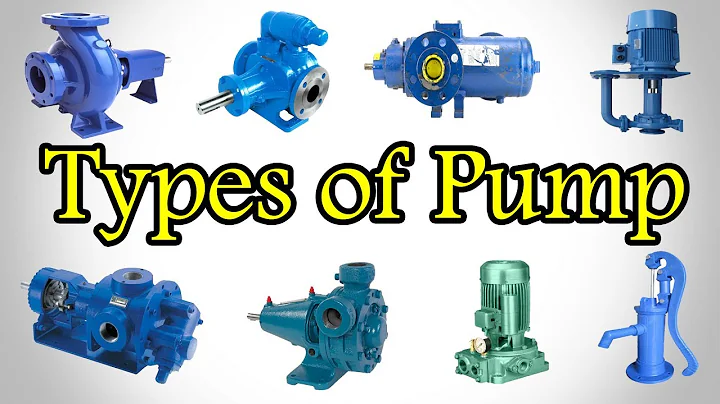
This procedure is applicable to the maintenance and overhaul of D-type, DA-type, GC-type and DG-type multi-stage centrifugal pumps commonly used in chemical enterprises. The pump is mainly used to feed boiler water and transport liquids that do not contain particulate matter and impurities and have physical and chemical properties similar to water. It can be used as a reference for other similar models of multi-stage centrifugal pumps.
1.2 Structural description
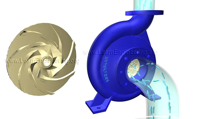
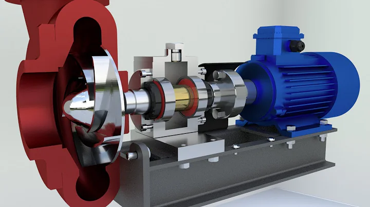
The fixed part of the pump consists of the water inlet section, the middle section, the water outlet section, guide vanes , bearing body and sealing device, etc.; the rotating part mainly consists of the pump shaft and several impellers mounted on the shaft. , a shaft sleeve, a balance plate to balance the axial thrust, and a coupling . Multiple impellers work in series, and the head of the same type of pump depends on the number of stages. The pump is directly driven by the motor via the coupling.
1.3 Technical performance
The main technical performance of the equipment is shown in Table 1.

2 Intact standard
2.1 Parts and components
2.1.1 The pump body and various parts and components are complete.
2.1.2 All connecting bolts are complete, the connections are tight, and there is no rust.
2.1.3 The safety protection devices are complete and stable.
2.1.4 The pressure gauge, ammeter and other instruments are complete and sensitive, the measuring range complies with the regulations and are calibrated regularly.
2.1.5 The inlet and outlet valves and lubrication and cooling system pipelines are neatly installed, clearly marked, and the oil mark, oil cup, etc. are complete and easy to use.
2.1.6 The installation and coordination of all parts comply with regulations.
2.1.7 The pump body, pump base and ancillary pipelines and pipe fittings are completely painted.
2.1.8 The foundation and base are complete and solid.
2.2 Long-distance travel performance
2.2.1 The oil circuit is smooth and well lubricated, and the "five-level" and "three-level filtration" are implemented.
2.2.2 The pressure and flow are stable, the temperature of each part is normal, and the current is stable.
2.2.3 The operation is smooth and there is no abnormal vibration, noise or other abnormal phenomena.
2.2.4 The capability can reach the nameplate output or verification capability.
2.3 Technical information
2.3.1 There are general assembly drawings or structural drawings of the pump, and there are drawings of wearing parts.
2.3.2 There are instructions for use, product certificate, and quality certificate.
2.3.3 Complete operating procedures, maintenance and inspection procedures.
2.3.4 The equipment files are complete and the data is accurate, including:
a. Installation and commissioning acceptance data;
b. Equipment operation records ;
c. Previous maintenance and acceptance records;
d. Records of equipment defects and accidents.
2.4 Equipment and environment
2.4.1 The equipment is clean and the surface is free of dust and grease.
2.4.2 The foundation is clean and tidy, there is no accumulation of water or debris on the surface, and the environment is neat and clean.
2.4.3 There is no leakage in the inlet and outlet valves, flange interface and the joints of each section of the pump body.
2.4.4 The leakage at the shaft seal shall not be greater than:
a. Packing seal, no more than 20 drops per minute in the initial stage, and no more than 40 drops per minute in the final stage;
b. Mechanical seal, there should be no leakage in the initial stage, and no leakage per minute in the final stage. More than 5 drops.
3 Equipment maintenance
3.1 Routine maintenance
3.1.1 Strictly follow the pump operating procedures to start, operate and stop, and keep operating records.
3.1.2 Check whether the lubricating oil in the lubricating parts meets the regulations every shift.
3.1.3 After the new bearings are replaced, the oil should be cleaned and changed after 100 hours of operation. After that, the oil should be changed every 1000-1500 hours of operation, and the grease should be changed every 2000-2400 hours of operation.
3.1.4 Check the bearing temperature frequently, it should not be higher than the ambient temperature 35℃, rolling shaft. The maximum temperature of the bearing shall not exceed 75℃; the maximum temperature of the sliding bearing shall not exceed 65℃. Check the motor temperature rise frequently.
3.1.5 Check the leakage at the shaft seal every shift. The packing seal should be kept at 10-20 drops per minute; for mechanical seals, they must be in good condition.
3.1.6 Always observe whether the pressure of the pump and the current of the motor are normal and stable. Pay attention to whether there is any abnormality such as noise in the pump. If any problems are found, deal with them promptly.
3.1.7 Always keep the pump and the surrounding area clean, and deal with runaway, leakage, dripping and leaking in a timely manner.
3.1.8 Maintenance personnel should be on duty regularly to check the operation of the equipment and deal with any problems found in a timely manner.
3.2 Regular inspection contents
For important pumps in the production system, regular inspections can be carried out according to the contents in Table 2.
Table 2
3.3 Common troubleshooting methods
Common troubleshooting methods are shown in Table 3.
3.4 Emergency parking
In case of one of the following situations, emergency shutdown should be carried out:
a. The pump suddenly vibrates violently;
b. Abnormal noises are made in the pump;
c. The current exceeds the rated value and does not fall after treatment. Invalid;
d. The pump suddenly fails to pump out
2. When the unit's condition monitoring method has met the conditions for predictive maintenance, it may not be restricted by this table after seeking approval from the superior authority.
Note: 1. Pumps with suction inlet diameter ≤100mm do not need overhaul, and the overhaul content will be incorporated into the intermediate repair.
4 Maintenance cycle and maintenance content
4.1 Maintenance cycle
Minor maintenance is 1 to 3 months, medium maintenance is 12 to 24 months, and major maintenance is 36 months.
4.2 Maintenance content
4.2.1 Minor repair
4.2.1.1 Inspect the packing seal and replace the packing.
4.2.1.2 Check the bearings and lubrication system, and replace the lubricating oil (grease).
4.2.1.3 Clean and inspect the cooling water system.
4.2.1.4 Clean and repair valves.
4.2.1.5 Check and align the coupling, adjust the axial clearance, and replace the wearing parts of the coupling.
4.2.1.6 Eliminate defects and leaks found during operation, and check and tighten all bolts.
4.2.2 Medium revision
4.2.2.1 Includes minor revisions.
4.2.2.2 Inspect the mechanical seal and replace parts.
4.2.2.3 Disassemble and clean the impeller, sealing ring, bushing, sleeve, guide vane, balance plate, balance ring and various parts for wear, corrosion and erosion, and repair or replace them.
4.2.2.4 Repair and scrape bearings, adjust the clearance, and replace the bearings.
4.2.2.5 Determine the static balance of the impeller.
4.2.2.6 Check the end surface contact between the impeller hub, bushing, balance hub and fastening nut of each section, and measure and correct the distance between impellers of each section.
4.2.2.7 Measure the runout of each part of the pump shaft and rotor components.
4.2.2.8 Check and adjust the clearance between various parts. Adjust the amount of rotor movement.
4.2.2.9 Verify the pressure gauge.
4.2.2.10 Repair the motor.
4.2.3 Overhaul of
4.2.3.1 Includes intermediate revision content.
4.2.3.2 Replace the impeller and guide vane.
4.2.3.3 Replace the pump shaft.
4.2.3.4 Each section of the pump body shall be inspected, appraised and necessary repairs made.
4.2.3.5 Adjust the level of the pump body.
4.2.3.6 Rust removal and anti-corrosion of equipment and ancillary pipelines.
5 Maintenance methods and quality standards
5.1 Pump body and base
5.1.1 The pump body should have no cracks, and the surface of the liquid flow channel should be smooth and free of blisters and pores. The parallelism of the joint surfaces between each section of the pump body is 0.1mm/m, and the joint surfaces and flanges are free of burrs and collision deformation.
5.1.2 The combination of pump body and impeller sealing ring adopts H7/h6.
5.1.3 The base and the foundation surface should be in tight contact, and the base installation level is: longitudinal 0.05mm/m and horizontal 0.10mm/m.
5.1.4 For pumps with axial expansion sliding pins, the sliding pins and pin grooves should be smooth and free of burrs.
5.1.5 When assembling, tightening the main connecting screw of the pump body should be symmetrical and the force should be even.
5.2 Guide vane and bushing
5.2.1 The liquid flow channel part of the guide vane should be smooth and the molding sand should be clean; there should be no serious through holes, cavitation, and other defects in the matching parts with the bushing .
5.2.2 The combination of guide vane and bushing adopts H7/n6 or H7/r6.
5.2.3 The diameter clearance between the guide vane bushing and the impeller hub is shown in Table 5. The clearance should be evenly checked on all sides, and the service wear limit should not exceed 3 times the maximum value in the table.
5.3 Pump shaft
5.3.1 The surface of the pump shaft shall be free of cracks, scratches, rust and other defects. If necessary, the pump shaft may be inspected for flaw detection during overhaul or replacement. Shaft wear can be repaired by electroplating, spray plating, brush plating and other methods.
5.3.2 The journal tolerance of the pump shaft, impeller and bushing is h6, the journal of the ball bearing is js6 or k6, the journal of the coupling is js6, the roundness of the journal is the same as the cylinder. The height should be no larger than half of its appropriate diameter.
5.3.3 Shaft diameter surface roughness: Assembly of impeller and sleeve, rolling bearing , sliding bearing, assembly of coupling
5.3.4 Using the journal at the bearing as the benchmark, use a dial indicator to check the assembled impeller , the radial circular runout of the shaft sleeve and coupling shaft segment should not be greater than 0.03mm.
5.3.5 The deviation of the keyway center line from the shaft center line shall not exceed 0.06 mm, and the skew shall not exceed 0.03mm/100mm.
5.4 Impeller
5.4.1 The inner wall of the liquid flow channel of the impeller should be clean and smooth, without sand, burrs and dirt. The transition between the processed surface and the non-processed surface of the flow channel entrance should be smooth.
5.4.2 The end face circular runout of the impeller hub to the shaft hole should not be greater than that specified in Table 6.
5.4.3 The skew of the center line of the impeller keyway and balance plate keyway to the center line of the shaft hole should not be greater than 0.03mm/100mm.
5.4.4 The newly installed impeller must be statically balanced. See Table 7 for the static balance tolerance. If the value in the table is exceeded, use the weight removal method to cut from both sides of the impeller. The thickness removed should not exceed 1/3 of the original wall thickness of the impeller, and the cut-off portion should smoothly transition to the impeller wall.
5.4.5 The diameter gap between the impeller and sealing ring is selected according to Table 8, and the surrounding gap should be kept uniform. The service wear limit shall not exceed 3 times the maximum value in Table 7.
5.5 Shaft sleeve
The outer circular surface of the shaft sleeve in contact with the sealing packing should be free of blisters, pores and other defects, and the surface roughness should be.
5.6 Balance plate device
5.6.1 The surface roughness of the contact plane between the balance plate and the balance ring is 0, and the contact is good.
5.6.2 The diameter gap between the balance plate hub and the balance ring is 0.2-0.6mm.
5.6.5 When the gap between the balance plate and the end face of the balance ring is 0.10-0.2, the impeller flow channel outlet should be aligned with the guide vane flow channel.
5.7 Rotor
5.7.1 The impeller, balance plate and shaft are matched with H7/h6.
5.7.2 The combination of the shaft sleeve, spacer sleeve and shaft should be H9/h9. The shaft sleeve, spacer sleeve and shaft cannot be made of the same material to avoid seizure.
5.7.3 The rotor is pre-assembled. Measure the distance between each impeller and the total distance. The error should not exceed ±1mm. If it exceeds, the length of the spacer sleeve should be adjusted or the length of the hub should be trimmed.
5.7.4 Check the radial runout of the outer circle of the impeller suction inlet. It should not be greater than that specified in Table 9.
5.7.5 The radial circular runout of the shaft sleeve, spacer sleeve, impeller hub and balance plate hub should not be greater than that specified in Table 10. The circular runout of the end face of the balance plate shall not be greater than that specified in Table 11.
5.7.6 The key and the side of the keyway should be tightly joined. The gasket is not allowed. The gap at the top of the key is 0.1-0.4mm.
5.7.7 For the multi-stage pump with speed n≥2950r/min and flow rate Q≥15m3/h, after the rotor is pre-assembled, a dynamic balance test should be carried out. The standard shall be in accordance with GB3215 "Refinery, Chemical and Petrochemical Processes" It is stipulated in "General Technical Conditions for Using Centrifugal Pump ".
5.8.1.1 The rollers and raceways of rolling bearings should be free of pits, pits and rust spots, the cage should be intact, the contact should be smooth, and the rotation should be noise-free.
5.8.1.2 The tolerance of the housing hole that matches the outer ring of the rolling bearing is H7.
5.8.1.3 The gap between the bearing gland and the rolling bearing end face should be no more than 0.10mm; the gap between the bearing gland and the rolling bearing end face on the expansion side of the shaft should leave sufficient clearance according to the length of the shaft and the medium temperature between the two bearings.
5.8.1.4 Special disassembly and assembly tools or press should be used to disassemble and assemble rolling bearings. When hot-installing the bearing, you can use a bearing heater or heat it in engine oil at 100-120°C before assembly. It is strictly forbidden to use direct flame heating or directly hit the bearing with a hammer.
5.8.2 Sliding bearing
5.8.2.1 The bearing alloy and the shell should be tightly and firmly connected, without defects such as shelling, cracks, pores, etc.; the surface should be smooth and clean, without scars and pits.
5.8.2.2 The tight force between the bearing bush and the bearing cap should be 0.02-0.04mm; the contact between the back of the lower tile and the bearing seat should be even, with the contact area reaching more than 60%.
5.8.2.3 The contact angle between the journal and the lower tile is in the range of 60o-90o in the middle, the contact surface is uniform, and there are at least 2-4 color spots per square centimeter in the paint inspection.
5.8.2.4 The bearing top clearance can be selected according to Table 12.
5.9 Shaft seal
5.9.1 Packing seal
5.9.1.1 The diameter gap between the packing bushing and gland and the uranium sleeve (or shaft) is selected according to Table 13, and the surrounding gap should be uniform.
5.9.1.2 The packing gland and the inner wall of the stuffing box (official account: Pump Steward) adopt H11/d11.
5.9.1.3 The diameter gap between the packing ring and the inner wall of the stuffing box is 0.15-0.20mm. The diameter gap between the packing ring and the sleeve (or shaft) should be increased by 0.3-0.5mm correspondingly compared with the value in Table 13.
5.9.1.4 The depth to which the gland is pressed into the stuffing box is generally 0.5-1 circle of packing height, and the minimum cannot be less than 5mm. The gland must not be skewed, and the tightness must be adjusted appropriately.
5.9.1.5 Note that the ring groove of the packing ring is aligned with the water seal hole on the wall of the stuffing box or slightly outside to ensure smooth water flow.
5.9.2 Mechanical seal
5.9.2.1 The radial circular runout of the sleeve or shaft where the mechanical seal is installed should comply with the requirements in Table 10, the surface roughness should be up to 10, and the outer diameter deviation should not exceed h6.
5.9.2.2 The axial movement of the shaft should not exceed ±0.5mm.
5.9.2.3 The flatness and surface roughness of the sealing end face in contact with the moving ring and the stationary ring should meet the requirements. Be careful when disassembling and assembling to avoid bumps and damage to the sealing surface; it is strictly forbidden to use a hand hammer or iron tool to knock.
5.9.2.4 During installation, the installation part and mechanical seal must be cleaned to prevent any impurities from entering the sealing part. The sealing surface can be coated with turbine oil or spindle oil during assembly.
5.9.2.5 The compression amount of the spring must be adjusted appropriately so that the compressed length of the spring is its working length.
5.10 Coupling
The alignment deviation of the two axes of the elastic sleeve pin coupling and the end face clearance of the coupling should comply with the requirements in Table 14.
6 Test run and acceptance
6.1 Preparation work before test run
6.1.1 Install the pressure gauge, vacuum gauge, ammeter and other instruments.
6.1.2 Remove all debris around the pump and clean up the site.
6.1.3 Check the tightening condition of the pump body and motor foot bolts, pump body tightening screw screw and other connecting bolts.
6.1.4 Add lubricating oil according to the regulations and check whether the cooling water system is smooth.
6.1.5 Check shaft seal .
6.1.6 Check the direction of rotation of the idle motor and install the coupling pin if correct.
6.2 Test run
6.2.1 Turn the pump for two weeks and pay attention to whether there is any abnormal sound in the pump and whether it rotates easily. Install the coupling protective cover immediately after turning the machine.
6.2.2 Introduce liquid into the pump and drain out the air.
6.2.3 Start according to the operating procedures of the pump. When the pump works at full speed and no abnormal conditions are found, it can be run continuously for test run.
6.2.4 The test run time is 4 hours, and should reach:
a. Smooth operation without noise, the lubrication and cooling system works normally;
b. Stable flow and pressure, reaching the nameplate capacity or verification capacity;
c. At rated Under certain head and flow conditions, the motor current does not exceed the rated value;
d. The temperature of each part is normal;
e. The vibration of the shell of the bearing part does not exceed the provisions of Table 2 of this regulation;
f. There is no leakage in each joint part and the accessory pipeline, and the shaft seal Leakage meets requirements.
6.3 Acceptance
If the quality of the pump meets the requirements of this regulation after maintenance, the maintenance records are complete and accurate, and the test run is normal, the acceptance can be processed according to regulations.
7 Maintenance and inspection safety precautions
7.1 Maintenance safety precautions
7.1.1 Do not place maintenance tools or any objects on the equipment.
7.1.2 When the pump is running, do not wipe the equipment near the rotating parts, and do not tighten the pressure parts bolt.
7.1.3 Keep the motor grounding wire intact, and be careful not to spray water on the motor when cleaning the site.
7.2 Safety precautions for maintenance
7.2.1 Relevant safety maintenance procedures must be completed according to regulations before maintenance.
7.2.2 Cut off the power and hang up the "no moving spleen" button.
7.2.3 Close the inlet and outlet valves or block the blind plate to isolate it from the system, and drain the remaining liquid.
7.2.4 When disassembling and cleaning equipment, replacement parts and maintenance tools must be placed neatly to ensure civilized maintenance.
7.2.5 Maintenance personnel must abide by the safe operating procedures of this type of work and the safety maintenance regulations of the enterprise.
7.3 Test run safety precautions
7.3.1 The test run should be carried out in an organized manner, and a dedicated person should be responsible for the safety inspection during the test run.
7.3.2 Starting and stopping the pump must be operated by a dedicated person, and the operator must hold a "Safe Work Certificate" for the position.
7.3.3 Strictly follow the starting and stopping procedures of the pump.
7.3.4 If abnormal sounds or other abnormalities are found during the test run, the vehicle should be stopped to check the cause and eliminate it before trying again.